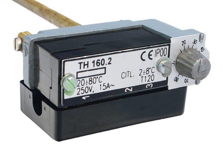
Thermostat series TH 160
Description
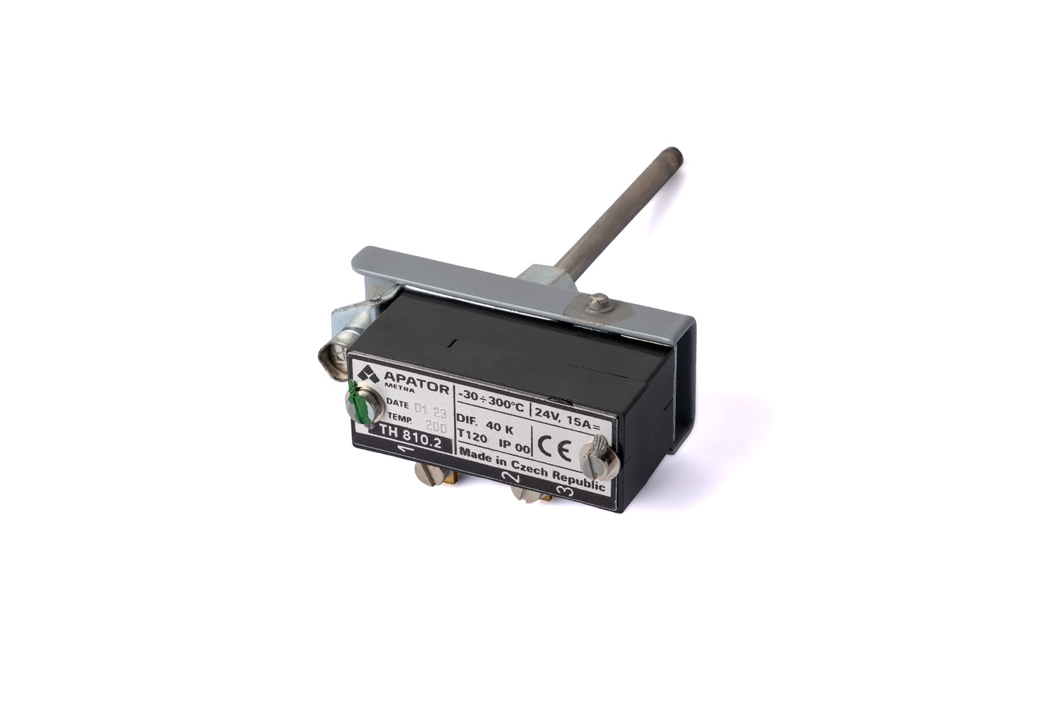
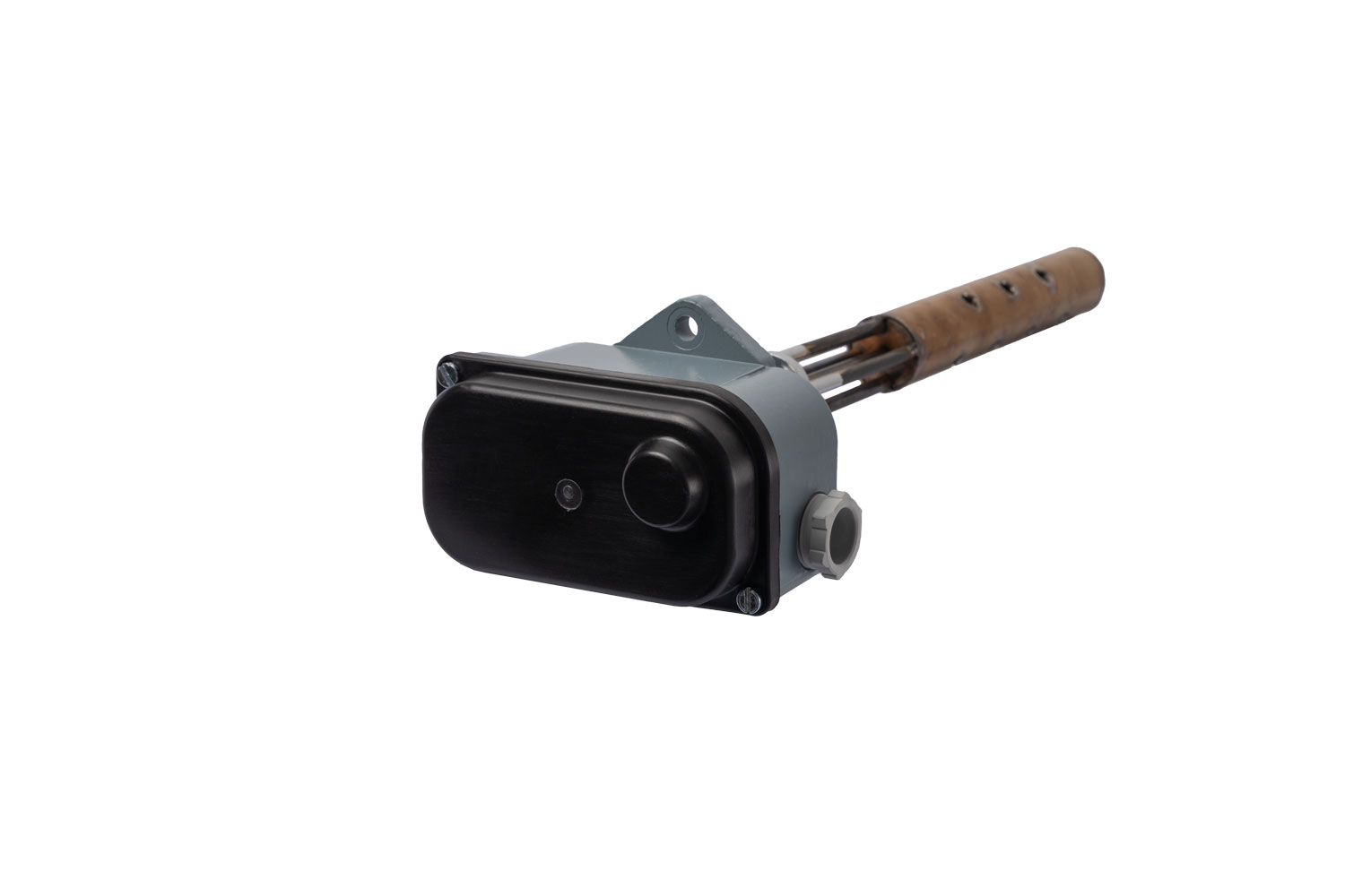
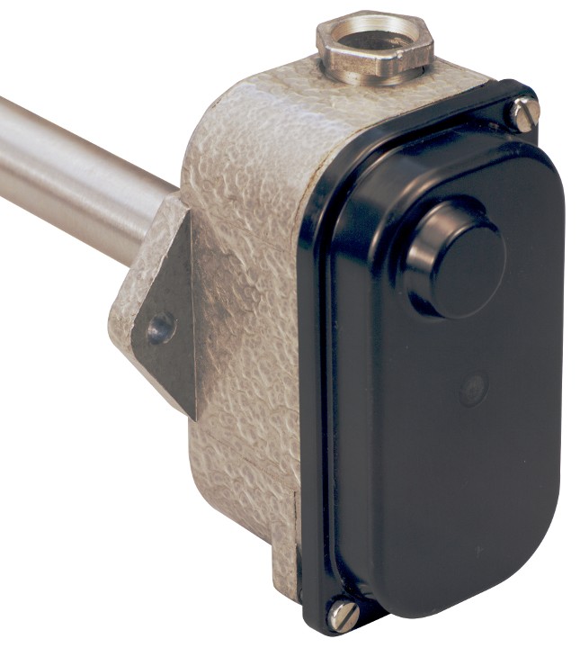
Thermostat consists of a stem (temperature sensor) and a switch head. Changes of sensor dilatation are transferred via lever to a switch. Thermostats are made either in disconnecting design (2 terminals) or in switching design (3 terminals). Screw terminal allow to connect wires with diameter up to 4 mm. Protective cable must be connected to protective terminal. The standard thermostat is equipped with terminal cover to prevent accidental contact. Requirement for thermostat without this cover must be indicated in order.
Avoid impacts on stem and head as well as stem deformations during installation. Thermostat well can be ordered as accessory.
Temperature setting
- Regulation knob - thermostats TH 160, TH 160.1, TH 160.2, TH 163, TH 164, TH 166, TH 167 and TH 169. Temperature can be changed in control range by user.
- In manufacturer according specification in order. Set temperature can not be changed by user (TH 162 and TH 165).
Technical data
| Setting accuracy | ±10 % from the highest rated switching temperature |
| Stem diameter | 8 mm |
| Max. temperature of the switch head | 120 °C |
| Weight | approx. 0,25 to 0,35 kg |
| Protection | IP 00 |
| Lifetime | 10 000 cycles |
| Type |
Control range [°C]
|
Switching difference [K] | Stem length L1 ±3 [mm] |
Thermostat length L ±3 [mm] |
Rated voltage, rated current | Number of terminals |
| TH 160 |
20-80
|
2÷8
|
315
|
388 |
250 V, 15 A AC
|
2
|
| TH 160.1 |
20-75
|
2÷8
|
315
|
388 |
250 V, 15 A AC
|
2
|
| TH 160.2 |
20-80
|
2÷8
|
315
|
388 |
250 V, 15 A AC
|
3
|
| TH 162 |
20-160
|
1÷16
|
100
|
164 |
250 V, 15 A AC
|
3
|
| TH 163 |
50-90
|
6÷16
|
100
|
173 |
250 V, 15 A AC
|
3
|
| TH 164 |
30-160
|
2÷10
|
160
|
233 |
250 V, 15 A AC
|
3
|
| TH 165 |
20-200
|
1÷10
|
160
|
224 |
250 V, 15 A AC
|
3
|
| TH 166 |
100-200
|
1÷10
|
200
|
273 |
250 V, 15 A AC
|
3
|
| TH 167 |
20-100
|
1÷10
|
250
|
323 |
250 V, 15 A AC
|
3
|
| TH 167.1 |
-10-50
|
1÷10
|
250
|
323 |
250 V, 15 A AC
|
3
|
| TH 169 |
60-120
|
2÷8
|
315
|
388 |
250 V, 15 A AC
|
2
|
Dimensional drawings
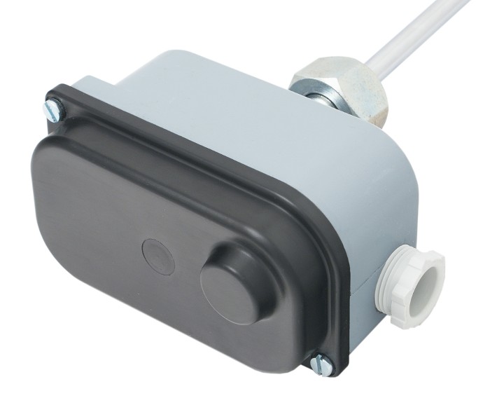
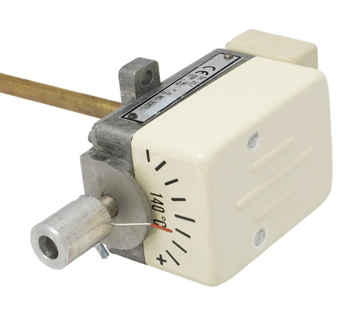
Photos of the product